Every living thing on earth needs water to survive. Human bodies are made up of more than 60 percent water! We use clean water to drink, grow crops for food, operate factories, and for swimming, surfing, fishing and sailing. Water is vitally important to every aspect of our lives.
As we all know that , Water is how much important for our and other life’s. So ,Monitoring the quality of surface water or any kind of water will help protect our waterways from pollution. For example:- Farmers can use monitoring information, to help him/her better manage their land and crops. Our local, state and national governments use monitoring information to help control pollution levels. We can use this information to understand exactly how we impact our water supply and to help us understand the important role we all play in water conservation.
Water Monitoring itself includes a monitoring of lots of parameters like viscosity , flow , pressure difference , and many more . But i would like to mainly give focus on the three most important parameters of water like COD , BOD , TSS. These three parameters of water gives the information about the dirtiness of water. So,measurement of these parameters is very important.
On Earth, Basically three types of water are presents:
Drinking Water Waste Water Surface Water
Drinking water or potable water is water of sufficiently high quality that can be consumed or used without risk of immediate or long term harm. It is provided by water supply networks or may be found in deep wells or springs.
Wastewater or sewage comprises liquid waste discharged by domestic residences, commercial properties, industry, and/or agriculture and can encompass a wide range of potential contaminants and concentrations. In the most common usage, it refers to the municipal wastewater that contains a broad spectrum of contaminants resulting from the mixing of wastewaters from different sources.
Surface water is water collecting on the ground or in a stream, river, lake, wetland, or ocean; it is related to water collecting as groundwater or atmospheric water.
In all of the above types of water , monitoring of the COD BOD TSS very important to analyzes the water usability for many purposes like drinking , use of water in chemical , and Nano-Fabrication types of industries , Semiconductor industries.
Before going into the technical details , Initially I would like to explain the proper meaning of the important water parameters are as follows:-
1. COD :- The chemical oxygen demand (COD) test is commonly used to indirectly measure the amount of organic compounds in water. Most applications of COD determine the amount of organic pollutants found in surface water (e.g. lakes and rivers) or wastewater, making COD a useful measure of water quality. It is expressed in milligrams per liter (mg/L), which indicates the mass of oxygen consumed per liter of solution.The basis for the COD test is that nearly all organic compounds can be fully oxidized to carbon dioxide with a strong oxidizing agent under acidic conditions. The amount of oxygen required to oxidize an organic compound to carbon dioxide, ammonia, and water denotes a COD value as shown by below equation:

2. BOD :- Biochemical oxygen demand (BOD) (also called biological oxygen demand) is the amount of dissolved oxygen needed (i. e., demanded) by aerobic biological organisms to break down organic material present in a given water sample at certain temperature over a specific time period. The BOD value is most commonly expressed in milligrams of oxygen consumed per litre of sample during 5 days of incubation at 20 °C and is often used as a surrogate of the degree of organic pollution of water.BOD is similar in function to chemical oxygen demand (COD), in that both measure the amount of organic compounds in water. However, COD is less specific, since it measures everything that can be chemically oxidized, rather than just levels of biodegradable organic matter.
3. TSS :- Total suspended solids (TSS) are particles that are larger than 2 microns found in the water column. Anything smaller than 2 microns (average filter size) is considered a dissolved solid. Most suspended solids are made up of inorganic materials, though bacteria and algae can also contribute to the total solids concentration.These solids include anything drifting or floating in the water, from sediment, silt,and sand to plankton and algae . Organic particles from decomposing materials can also contribute to the TSS concentration. As algae, plants and animals decay, the decomposition process allows small organic particles to break away and enter the water column as suspended solids. Even chemical precipitates are considered a form of suspended solids. Total suspended solids are a significant factor in observing water clarity . The more solids present in the water, the less clear the water will be.
To measure all these water parameters (COD , BOD , TSS) , there are lots of water monitoring techniques are available in the market are as follows:-
1. TOC :- This Techniques is based on the principle of the oxidation method . It takes some water sample into its chamber oxidise it at some high temperature and evolved CO2 gas is measured by either of the two available techniques like conductivity measurements or NDIR principle. This amount of measurements of CO2 is correlated with the COD , BOD values.
2. Ion Selective Electrodes (ISE):- This is a Technique which is not mostly used for the measurement of the COD , BOD ,TSS , because this technique is highly selective to particular ions and measurements of the all ions which contribute in COD , BOD is not possible by this principle. Secondly, in this principle a lot of drifts are also present due to temperature change , due to matrix interference or complex formation within or on the electrodes which degrades the working life of electrodes. As it work like a Electrolytic cell where the potential of the working electrodes ( highly selective in nature) get changed with reference from reference electrodes , when the target ions comes in contact with working electrodes.
3. Colorimetric :- This method is purely on the Lab testing. It involves lot of mechanical work , use of lots of reagents. The principle of working of this is to create first a carbonate or permanganate ions , when the sample get treated with the reagents. And than to analyze the sample on each wavelength corresponding absorbance value is correlated with the concentration of the COD , BOD parameters.
4. UV – VIS Spectrophotometer :- This techniques is basically a measurements of the absorption corresponding to wavelength of UV & VIS ranges of electromagnetic spectrum (189 nm to 720 nm) .In this technique the absorbance value is correlated with the concentration of organic consumed , bacteria ,& suspended solids present in a water sample, which is denoted by COD , BOD , TSS. This technique is elaborate in more details in the following sections
Out of the four above , It has been researched that , UV – VIS spectrophotometer technology found to be one of the best possible technology for the measurement of the water parameters. Because of its low maintenance routine check up, low cost, available for online monitoring purpose , No use of reagents , easy to install and understand & The most important thing is that result is almost correctly correlated with the actual results.
The details explanation about components of UV-VIS and its principle are given in following points:-
UV-VIS SPECTROPHOTOMETER
Spectrophotometry is the quantitative measurement of the reflection or transmission properties of a material as a function of wavelength.
There are two major classes of devices: single beam and double beam. A double beam spectrophotometer compares the light intensity between two light paths, one path containing a reference sample (may be AIR) and the other the test sample. A single-beam spectrophotometer measures the relative light intensity of the beam before and after a test sample is inserted
Principle of Spectrophotometry
Its is based on the Principle of Beer Lambert’s Law. The Beer-Lambert law relates the attenuation of light to the properties of the material through which the light is travelling. For each wavelength of light passing through the spectrometer, the intensity of the light passing through the reference cell is measured. This is usually referred to as Io . The Beer-Lambert law is the linear relationship between absorbance and concentration of an absorber of electromagnetic radiation. The general Beer-Lambert law is usually written as: A = aλ · b · c , (where A is the measured absorbance, aλ is a wavelength-dependent absorptivity coefficient, b is the path length, and c is the analyte concentration). If multiple species that absorb light at a given wavelength are present in a sample, the total absorbance at that wavelength is the sum due to all absorbers is: A = (ε1 · b · c1) + (e2 · b · c2) + …. , where the subscripts refer to the molar absorptivity and concentration of the different absorbing species that are present. Experimental measurements are usually made in terms of transmittance (T), which is defined as: T = P/Po where P is the power of light after it passes through the sample and Po is the initial light power(passed through any kind of reference medium). The relation between A and T is:
A = − log(T) = − log(P/Po)
Instrumentation of UV-visible spectrophotometer
Types of UV-visible spectrophotometer
1. Single beam spectrophotometer

2. Double beam spectrophotometer

Advantages of double beam instruments over single beam instruments
Single beam spectrophotometer is inconvenient because
1. The sample and blank must be placed alternately in the light path.
2. For measurements at multiple wavelengths, the blank must be run at each wavelength.
In double beam instruments
1. The absorption in the sample is automatically corrected for the absorption occurring in the blank, since the readout of the instrument is log the difference between the sample beam and the blank beam
2. Automatic correction for changes of the source intensity and changes in the detector response with time or wavelength because the two beams are compared and measured at the same time
3. Automatic scanning and continuous recording of spectrum (absorbance versus wavelength).
Components of Spectrophotometer
1. Continuous sources emit radiation of all wavelengths within the spectral region for which they are to be used.
2. Sources of radiation are stable and of high intensity.
Chemometry and Wavelength Selection

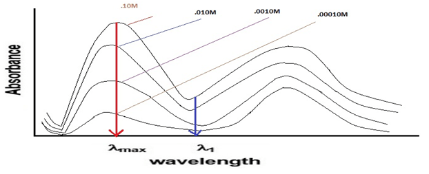
In spectrophotometery , each water sample in the quartz cuvette is analyzed corresponding to each wavelength. A light from the source i.e visible and ultraviolet source is passed through a monochromator or filter ( behaves as a wavelength splitter i.e it passes one by one wavelength through the sample , corresponding to which absorption values is calculated).To find and correlate, the absorption reading with the water parameters or concentration (COD, BOD , TSS) for quantitative analysis, its is required to choose wavelength and corresponding absorption values using these following conditions:-Wavelength should be chosen to give the highest possible sensitivity. This can be achieved by selecting lmax or in general the wavelengths at which the absorptivity is relatively high.
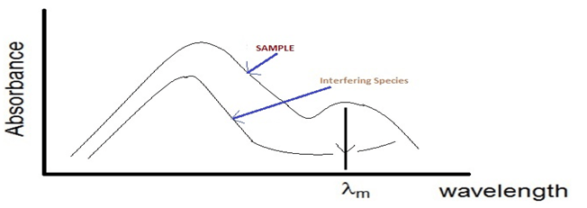
λmax – wavelength where maximum absorbance occurs
By performing the analysis at such wavelengths, it will be sure that the lowest sample concentration can be measured with fair accuracy. For example, the lowest sample concentration (10-5 M) can be measured with good accuracy at lmax, while at other wavelength (λ1), it may not be detected at all.
2.It is preferable to choose the wavelength at which the absorbance will not significantly change if the wavelength is slightly changed, i.e., Change in A / Change in l is minimum. At a wavelength corresponding to broad horizontal band on the spectrum (band A), the radiation is mainly absorbed to the same extent (change in A / change in l ~zero). However on a steep portion of the spectrum (band B), the absorbance will change greatly if the wavelength is changed (Change in A / Change in l is large) . Thus on repeating the absorbance measurements, you might get different readings and the precision of the measurements will be poor.
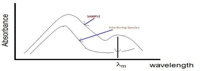
3.If the solution contains more than absorbing species, the wavelength should be chosen, whenever possible, in region at which the other species does not absorb radiation or its absorbance is minimum. By this way, the second species does not interfere in the determination.
Chemometric Correlation for UV-VIS Analyzers
The field of science dealing with the correlation of absorbance spectra to concentration information is often called “Chemometrics”.
When correlating a set of UV-VIS absorbance sample data to concentration parameters like BOD or COD we are actually performing a “chemometric correlation”.
It is important to note that all chemometric correlation without exception require a “training set” of reference samples to provide the correlating coefficients relating the spectral absorbance data to the concentration data.
There are many methods for the correlation scenario. Below i have explained one method to find out the correlation coefficients called as Inverse Least Squares (ILS) correlation Method.
Inverse Least Squares (ILS) Correlation Method- for finding coefficients for Spectrum of Water Matrix
•ILS is a method that can be used to measure the concentration of an analyte in samples in which the spectrum of the analyte in the sample is not known beforehand. Whereas the classical least squares method models the signal at each wavelength as the sum of the concentrations of the analyte times the analytical sensitivity, the inverse least squares methods use the reverse approach and models the analyte concentration c in each sample as the sum of the signals A at each wavelength times correlation coefficients m that express how the concentration of that components is related to the signal at each wavelength:cs1 = mw1As1,w1 + mw2As1,w2+ mw3As1,w3 + … for all w wavelengths, cs2 = mw1As2,w1 + mw2As2,w2 + mw3As2,w3 + … , and so on for all ‘s’ samples.
In matrix form C = AM, where C is the s-length vector of concentrations of the analyte in the s samples, A is the w x s matrix of measured signals at the w wavelengths in the s samples, and M is the w-length vector of correlation coefficients.
Now, suppose that you have a set of standard samples that are typical of the type of sample that you wish to be able to measure and which contain a range of analyte concentrations that span the range of concentrations expected to be found in other samples of that type. This will serve as the correlation set. You measure the spectrum of each of the samples in this correlation set and put these data into a w x s matrix of measured signals A. You then measure the analyte concentrations in each of the samples by some reliable and independent analytical method and put those data into a s-length vector of concentrations C. Together these data allow you to calculate the correlation vector M by solving the equation M = (ATA)-1ATC.
•(Note that ATA is a square matrix of size w, the number of wavelengths). This correlation vector can be used to compute the analyte concentrations of other samples, which are similar to but not in the correlation set, from the measured spectra of the samples:
CWxS = AWxS *MSxW
•Clearly this will work well only if the analytical samples are similar to the correlation set. The advantage of this method is that the spectrum of an unknown sample can be measured much more quickly and cheaply than the more laborious standard reference methods that are used to measure the correlation set, but as long as the unknowns are similar enough to the correlation set, the concentrations calculated by the above equation will be accurate enough for many purposes.
Note :- Here the MATRIX is of WxS size,Instead of this we can also take matrix size of SxW, as given below CSxW = ASxW * MWxS
Sample compartment (cells)
1. For Visible and UV spectroscopy, a liquid sample is usually contained in a cell called a cuvette through which light passed.
2. Glass is suitable for visible but not for UV spectroscopy because it absorbs UV radiation. Quartz can be used in UV x as well as in visible spectroscopy.
Detectors
The detectors in the Spectrophotometery detect the each of the wavelength of light after passes through the sample(placed in cuvette) and without sample (Reference sample). When the wavelength of light fall on this detector , corresponding to which current flows which is directly proportional to the intensity of the light (on each wavelength).
There are Two types of detector present basically are as follows :-
1. Phototube:- Phototube emits electrons from a photosensitive, negatively charged cathode ,when struck by visible or UV radiation. The electrons flow through vacuum to an anode to produce current which is proportional to radiation intensity.

2. Photomultiplier Tube :- It is a very sensitive device in which electrons emitted from the photosensitive cathode strike a second surface called dynode which is positive with respect to the original cathode. Electrons are thus accelerated and can knock out more than one electrons from the dynode.If the above process is repeated several times, so more than 106 electrons are finally collected for each photon striking the first cathode.

Limitation of Spectrophotometery
Beer-Lambert’s law proves a direct correlation between the absorbance (A) of a molecule to the concentration (c) and the path length (b) of the sample. This relationship is a linear for the most part. However, under certain circumstances the Beer Lambert relationship breaks down and gives a nonlinear relationship. These deviations from the Beer Lambert law can be classified into three categories:
1. Real Deviations – These are fundamental deviations due to the limitations of the law itself.
2. Chemical Deviations– These are deviations observed due to specific chemical species of the sample which is being analyzed.
3. Instrument Deviations – These are deviations which occur due to how the absorbance measurements are made.
I shall attempt to clarify each of these with suitable examples so as to improve about understanding of spectroscopy.
Real Limitation and Deviation of Beer-Lambert Law
Beer law and Lambert law is capable of describing absorption behavior of solutions containing relatively low amounts of solutes dissolved in it (<10mM). When the concentration of the analyte in the solution is high (>10mM), the analyte begins to behave differently due to interactions with the solvent and other solute molecules and at times even due to hydrogen bonding interactions.
A. At high concentrations, solute molecules can cause different charge distribution on their neighboring species in the solution. Since UV-visible absorption is an electronic phenomenon, high concentrations would possibly result in a shift in the absorption wavelength of the analyte. At times, even electrolyte concentrations (such as those present in buffers) play an important role in altering the charge distributions and affecting UV-visible absorbance. Some large ions or molecules show deviations even at very low concentrations. For e.g. methylene blue absorptivity at 436 nm fails to observe Beer Lambert law even at concentrations as low as 10μM.
B.High analyte concentrations can also possibly alter the refractive index (η) of the solution which in turn could affect the absorbance obtained. If the addition of solute causes a significant change in the refractive index of the solution a correction to the Beer Lambert formula can be placed as:
B.A = εbc (η2 + 2)2
This correction is normally not required below concentrations of 10mM.
Chemical Deviations and Limitations to Beer-Lambert Law
Chemical deviations occur due to chemical phenomenon involving the analyte molecules due to association, dissociation and interaction with the solvent to produce a product with different absorption characteristics. For example, phenol red undergoes a resonance transformation when moving from the acidic form (yellow) to the basic form (red). Due to this resonance, the electron distribution of the bonds of molecule changes with the pH of the solvent in which it is dissolved. Since UV-visible spectroscopy is an electron-related phenomenon, the absorption spectrum of the sample changes with the change in pH of the solvent.
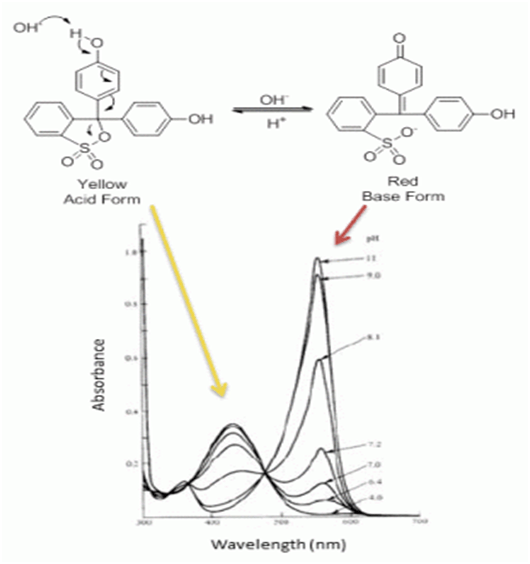
Acid and Base forms of phenol red along with their UV spectra at different pH demonstrates chemical deviations of Beer-Lambert law in UV-Visible spectroscopy
Instrumental Deviations and Limitations to Beer-Lambert Law
A. Due to Polychromatic Radiation (Also the reason why absorbance measurements are taken at the wavelength of maximum absorbance λmax) Beer-Lambert law is strictly followed when a monochromatic source of radiation exists. In practice, however, it is common to use a polychromatic source of radiation with continuous distribution of wavelengths along with a filter or a grating unit (monochromators) to create a monochromatic beam from this source. For example (see figure below), consider a molecule having molar absorptivities ε’ and ε” at wavelengths λ’ and λ”. The absorbance (Am) for such a species can be calculated as:

Equation to calculate absorbance of a sample with polychromatic light source.
When the molar absorptivities are the same at both wavelengths (i.e. ε’ = ε”) , the relationship between absorbance and concentration follows Beer-Lambert law to obtain a straight line. However, as the difference between ε’ and ε” increases, the deviations from linearity also increases.
Why absorption measurements are taken at wavelength of maximum absorbance λmax?
If the band of wavelength selected on the spectrometer is such that the molar absorptivities of the analyte is essentially constant, deviations from Beer-Lambert law are minimal. However, if a band is chosen such that the molar absorptivity of the analyte at these wavelengths changes a lot, the absorbance of the analyte will not follow Beer-Lambert law. It is observed (as demonstrated in the figure below) that the deviations in absorbance over wavelengths is minimal when the wavelength observed is at the λmax. Due to this reason absorption measurements are taken at wavelengths.
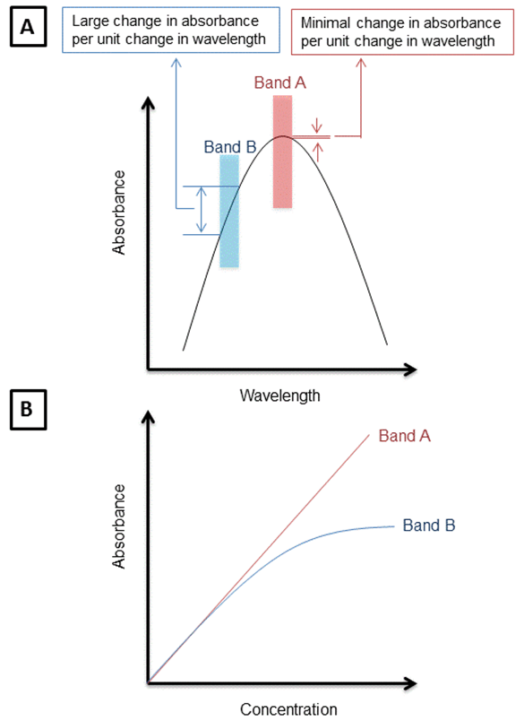
Figure A: Shows the difference in deviations in absorbance when values are obtained at maximum wavelength of absorbance (band A) vs other wavelengths of absorbance (band B). Figure B: shows the deviations in Beer-Lambert law due to observations made at wavelengths other than lambda max.
B. Due to Presence of Stray Radiation
Stray radiation or scattered radiation is defined as radiation from the instrument that is outside the nominal wavelength band selected. Usually the wavelength of the stray radiation is very different from the wavelength band selected. It is known that radiation exiting from a monochromator is often contaminated with minute quantities of scattered or stray radiation. Usually, this radiation is due to reflection and scattering by the surfaces of lenses, mirrors, gratings, filters and windows. If the analyte absorbs at the wavelength of the stray radiation, a deviation from Beer-Lambert law is observed similar to the deviation due to polychromatic radiation.
C. Due to Mismatched Cells or Cuvettes
If the cells holding the analyte and the blank solutions are having different path-lengths, or unequal optical characteristics, it is obvious that there would be a deviation observed in Beer-Lambert law. In such cases when a plot of absorbance versus concentration is made, the curve will have an intercept k and the equation will be defined as:
A = εbc + k
In today’s instrument this problem is generally not observed, however if it is present, appropriate linear regression to quantify this deviation must be made.

